1 / 3

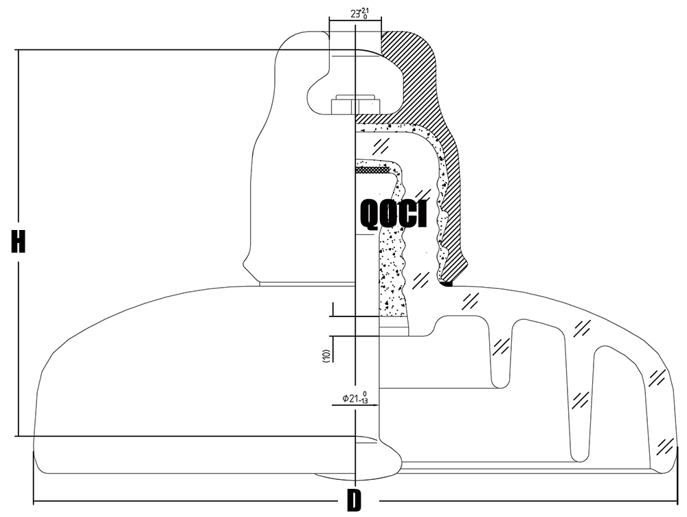
| Designation / Metric Parameter | Value / Type Specification | |
|---|---|---|
| Domestic Designation | U420BP | |
| Reference Code | — | UG420B205/620H |
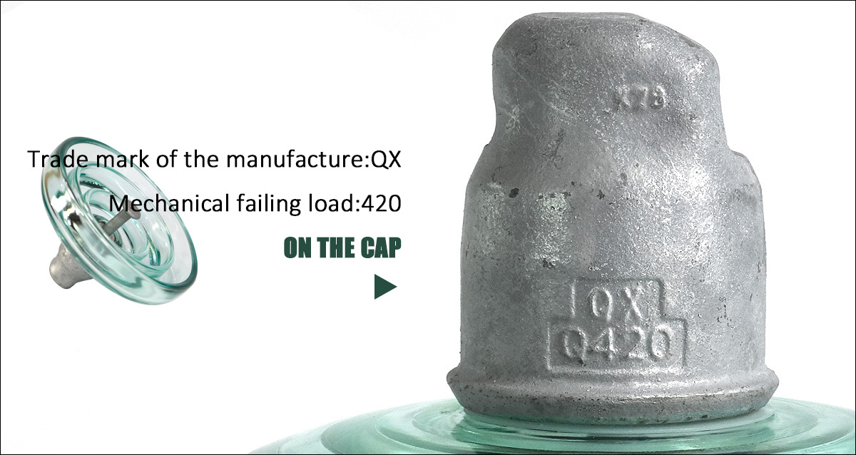
| Mechanical failing load | kN | 420 |
| Nominal Diameter D | mm | 300 |
| Nominal Spacing P | mm | 205 |
| Creepage distance L | mm | 620 |
| Socket coupling | mm | 28 |
| Wet power frequency withstand voltage | kV | 55 |
| Dry lightning impulse withstand voltage | kV | 140 |
| Power frequency puncture voltage | kV | 140 |
| Radio interference voltage (10kV 1MHz) | µv | 50 |
| Corona visual test P/C | kV | 18/22 |
| Power frequency electric arc voltage | kA | 0.12S/20kA |
| Impulse puncture voltage | P.U | 2.8 |
| Net weight per unit | kg | 15.8 |
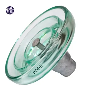
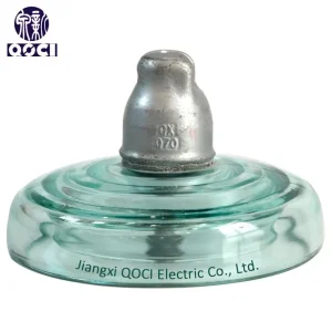
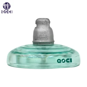
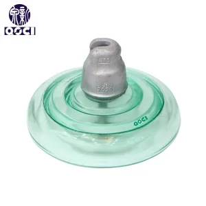
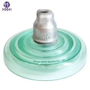
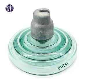
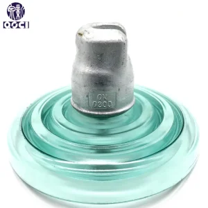
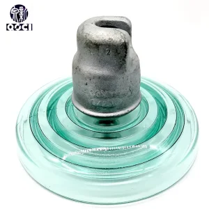
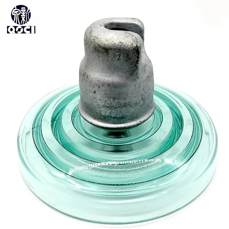
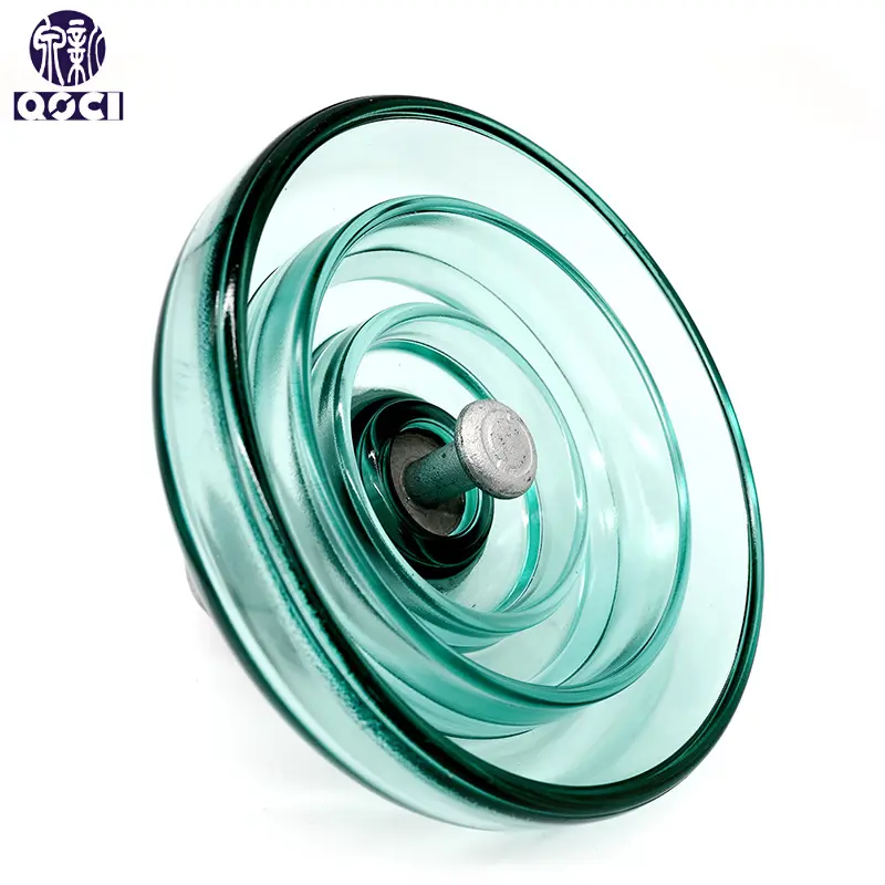
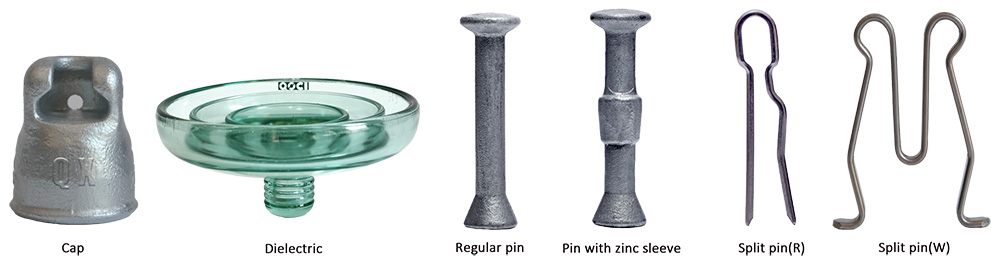
Suspension insulators consist of the following elements:
Additionally, the insulator cap features a stainless steel or phosphor bronze locking device (split pin) which ensures secure unit coupling.
Pins can also be equipped with an anti-corrosion zinc sleeve (sacrificial anode) upon request. This zinc protection is highly recommended for insulation lines operated in heavily polluted or coastal areas.
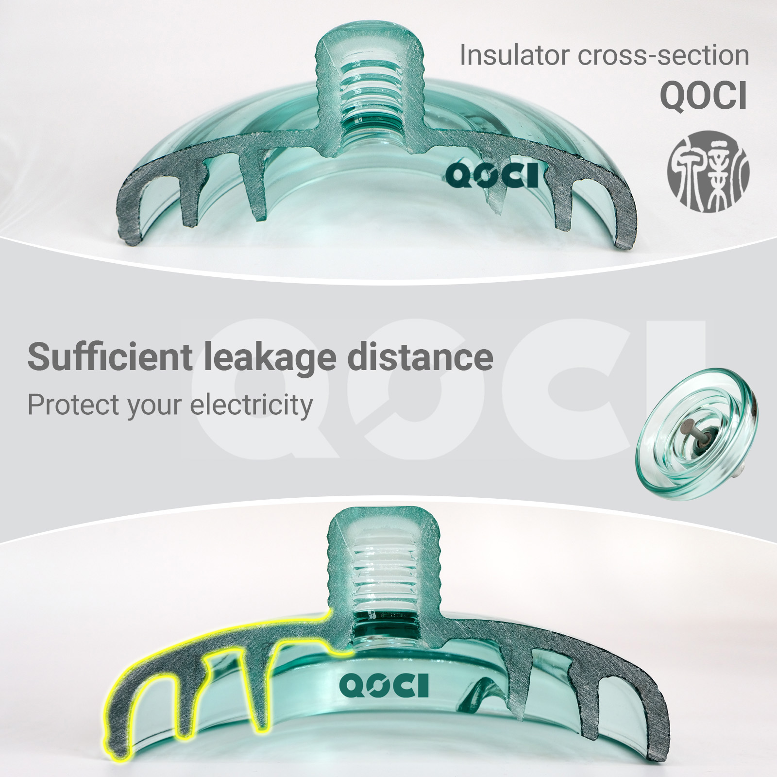
Under long-term electrical stress, contaminants deposited on the surface can trigger localized electrical arcs. This phenomenon can lead to surface carbonization (electrocorrosion) of standard insulators.
This design provides ample creepage distance to disperse the electric field strength, substantially lowering the risk of local discharge and extending the service life of the component.
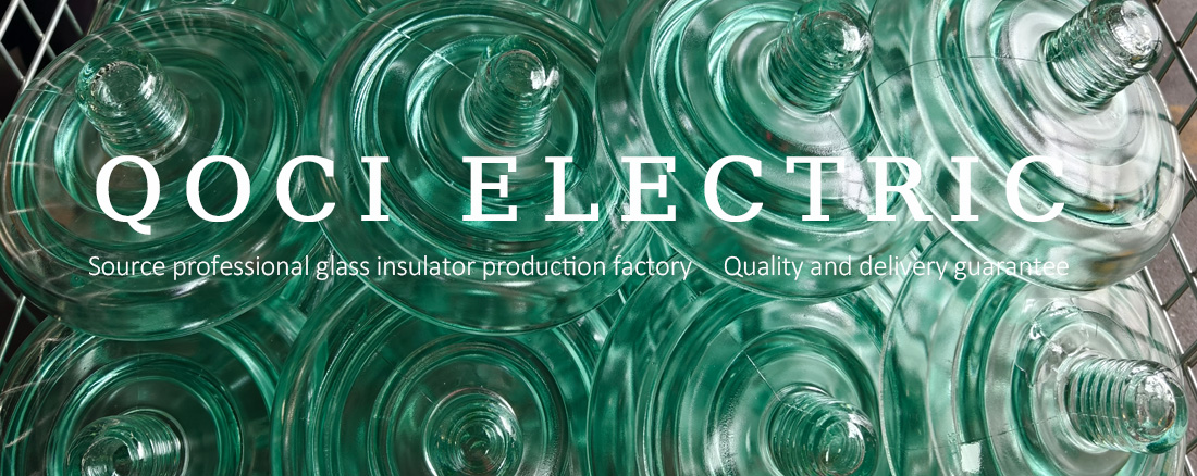
"U" stands for Disc Suspension Insulator, "420" indicates a rated mechanical failing load of 420kN, "B" indicates the Ball and Socket connection style, and "P" represents the Anti-Pollution design, suitable for environments prone to contamination.
The nominal creepage distance is 620mm, which provides superior tracking resistance and voltage withstand performance in polluted operating environments.
The insulator is designed and tested in accordance with IEC60383-1:1993 (MOD) / GB/T1001.1 standards, and its connection coupling interfaces match GB/T4056-2008 (IEC60120:1984, MOD) and BS 3288 Part III specifications.
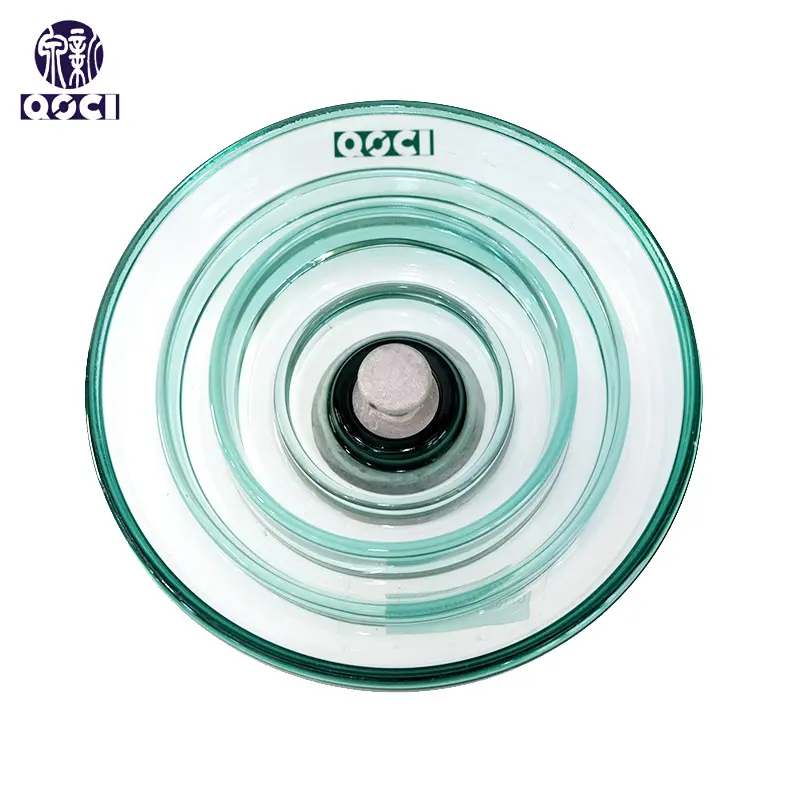
The shell configuration features a wide under-rib profile that maximizes the path for leakage currents (creepage distance). This structure prevents the formation of continuous conductive contaminant layers and dampens local electric fields, reducing the probability of dry band flashovers and electrocorrosion.
By default, the U420BP model utilizes an R-pin locking device made of corrosion-resistant stainless steel or bronze. A W-pin configuration can also be accommodated based on specific client engineering requirements.
Yes. For installations in coastal areas or heavy industrial zones, a hot-dip galvanized steel pin equipped with an anti-corrosion zinc sleeve (sacrificial anode) can be supplied to extend the overall service life of the connection points.